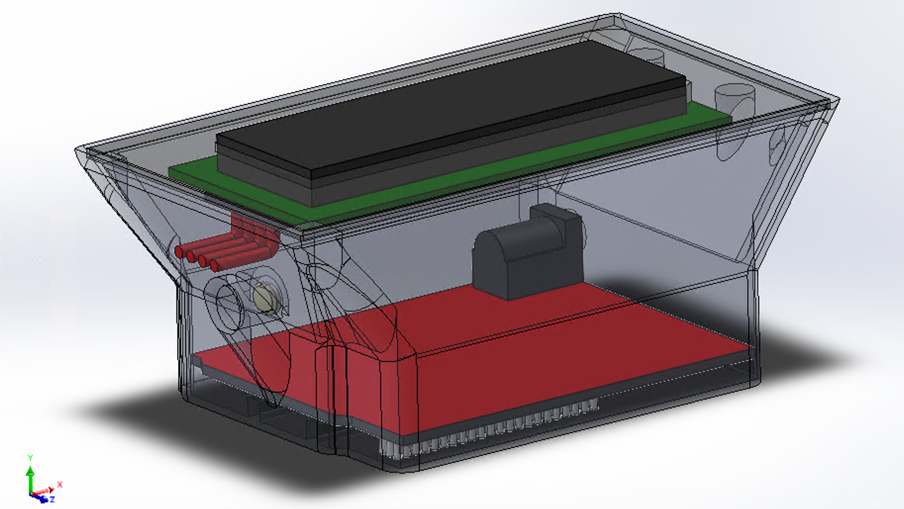
Solidworks Assembly Overview
Colors are used to differentiate components, with most parts being 3-D printed. The design uses a standard 9g servo motor, 608 skateboard bearings, and 1/4in wooden dowels. There is an A2122 brushless DC motor, and space in the center for whatever size battery and electronic speed controller are desired.
The most complex system is the steering assembly. Each wheel is directly mounted to a skateboard bearing for minimal rolling friction. The bearings are mounted within the yellow component, and are restricted to a single degree of freedom. The maroon connecting rod attaches to both bearing mounts, and ensures that the wheels turn equally. A single 9g servo is mounted on top of the assembly. With proper electronic control, the servo is actuated to steer the car. This design allows the wheels 120° of freedom to turn the car, and was modeled from scratch for this project.
Front Steering Assembly
Front Steering Demonstration
The drive system for the car uses a single A2122 brushless DC motor. A pinion gear is mounted to the motor's shaft, which in turn directly drives the rear wheel. This design allows for a very high torque output to the rear tire. Additionally, the translucent green component can be repositioned to accommodate different gear ratios. This adjustability allows for future iterations and design changes to be incorporated easily.
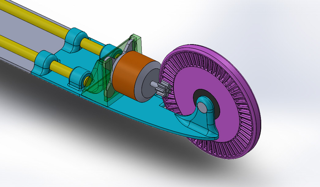
Rear Drive Assembly
In order to prevent rear wheel wobble and improve the performance of the pinion gear, a support structure was included. This structure, circled in red below, drastically improved the performance of the drive system, and the stability of the rear wheel.
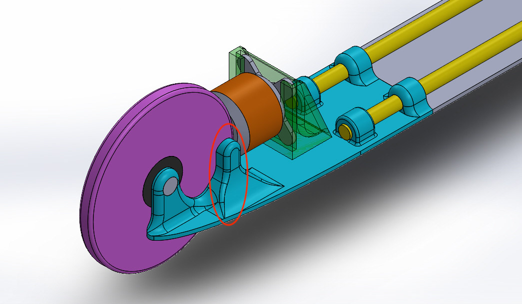
Rear Wheel Support Detail
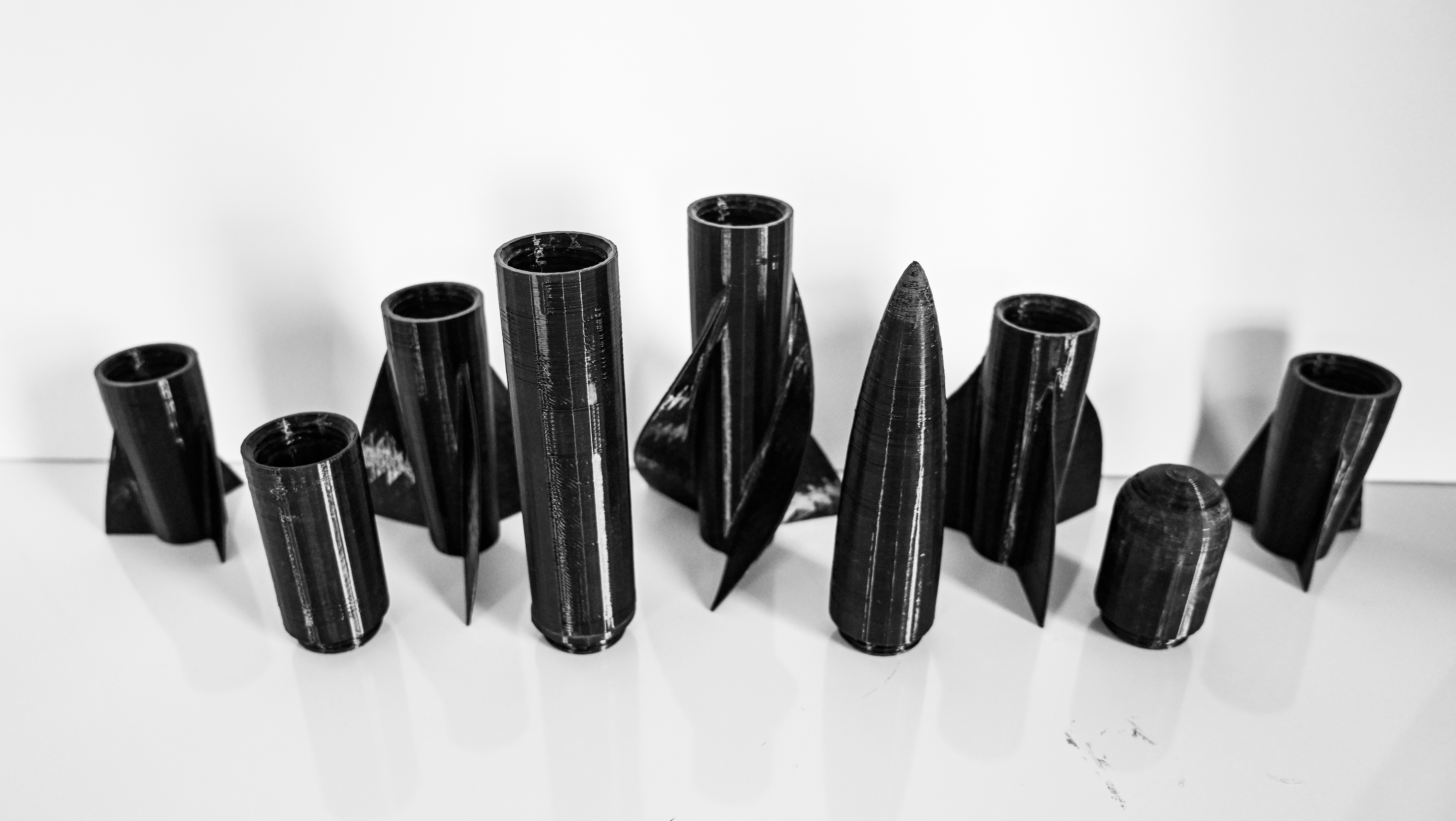
After printing, the components are ready to be assembled and glued in place. The steering servo motor and brushless dc motor are held in place with glue, but all other parts are pressure-fit to stay together.
Once fully assembled, electronics can be added, and the car is ready to run!